

Office, nozzle and venturi flowmers use the Bernoulli equation to calculate fluid flow using pressure difference through flow obstructions.
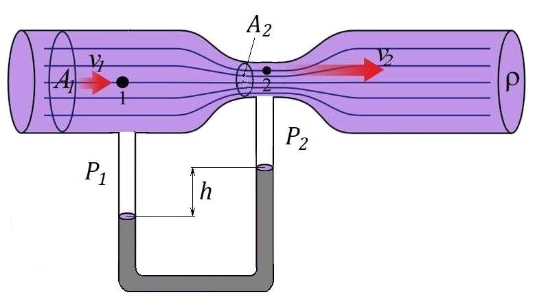
In a flow meter based on the Bernoulli equation, the downstream pressure after an obstruction will be less than the previous pressure. To understand hole, nozzle and venturi meters it is necessary to explore Bernoulli's equation.
Bernoulli's equation
Assuming a horizontal flow (disregarding the slightest difference in elevation between the measuring points), Bernoulli's equation can be modified to:
p 1 + 1/2 P V 1 2 = p 2 + 1/2 P V 2 2 (1)
Where
p = Pressure (PA, PSF (LB/FT 2 ))
r = density (kg/m 3 , slugs /ft 3 )
v = Flow speed (m/s, feet/s)
The equation can be adapted to the vertical flow by adding elevation heights :
p 1 + 1/2 P V 1 2 + c h 1 = p 2 + 1/2 P V 2 2 + c h 2 (1b)
Where
γ = specific fluid weight (kg/m 3 , slugs/ft 3 )
H = elevation (m, feet)
Assuming uniform speed profiles in the upstream and downstream flow - the continuity equation can be expressed as
q = v 1 A 1 = v 2 A 2 (2)
Where
q = flow (m 3 /s, ft 3 /s)
A = Flow Area (m 2 , ft 2 )
Combining (1) e (2) , assuming A 2 < A 1 , The “ideal” equation is obtained:
q = A 2 [ 2(p 1 – p 2 ) / P (1 - (A 2 / A 1 ) 2 ) ] 1/2 (3)
For a given geometry (A) , the flow can be determined by measuring the pressure difference p 1 – p 2 .
The theoretical flow q It will be in the smaller practice ( 2 – 40%) Due to geometric conditions.
The ideal equation (3) can be modified with a discharge coefficient:
q = c d A 2 [ 2 (p 1 – p 2 ) / P (1 - (A 2 / A 1 ) 2 ) ] 1/2 (3B)
Where
c d = Download coefficient
O Discharge coefficient c d It is a function of the size of the jet - or opening of the hole - the
Area Reason = A vc / A 2
Where
A vc = EM Area “Vena Contract” (M 2 , ft 2 )
” Contract vein ”It is the minimum jet area that appears downstream of the restriction. The viscous effect is usually expressed in terms of the non -dimensional parameter Reynolds Number - Re .
Due to benalli and the continuity equation, fluid speed will be maximum and the minimum pressure on ” Contract vein “After the measurement device, the speed will decrease to the same level as before obstruction. The pressure recovers to a pressure level below the pressure before the obstruction and adds a load loss to the flow.
The equation (3) can be modified with diameters for:
q = c d (π / 4) d 2 2 [ 2 (p 1 – p 2 ) / P (1 - d 4 ) ] 1/2 (4)
Where
D 2 = hole, venturi or inner diameter of the nozzle (m, ft)
D 1 = Diameter of the upstream pipe and downstream (m, feet)
d = diameter ratio d 2 / D 1
P = 3.14…
The equation (4) can be modified for fluid mass flow simply by multiplying with density:
m = c d (π / 4) d 2 2 P [2 (p 1 – p 2 ) / P (1 - d 4 ) ] 1/2 (5)
Where
M = mass flow (kg/s)
When measuring mass flow in gases, it is necessary to consider pressure reduction and change in fluid density. The above formula can be used with limitations for applications with relatively small pressure and density changes.
The hole plate
The hole meter consists of a flat hole plate with a circular hole drilled in it. There is a pressure driving upstream and another downstream. There are generally three methods to put the taps. The coefficient of a meter depends on the position of the taps.
- FLANGE LOCATION - Pressure Taking location 1 inch the amount and 1 inch downstream of the face of the hole
- Location " Contract vein ” - Location of pressure socket 1 pipe diameter (actual inside) to upstream and 0,3 a 0,8 tube diameter downstream of the face of the hole
- Tube location - pressure socket location 2,5 times the nominal diameter of the upstream tube and 8 times the nominal diameter of the tube downstream of the face of the hole
Or download coefficient - c d - It varies considerably with the changes in the area ratio and the number of Reynolds. A discharge coefficient c d = 0,60 It can be considered standard, but the value varies notably at low values of the number of Reynolds.
| Download coefficient – c d | ||||
|---|---|---|---|---|
| Diameter ratio d = D 2 / D 1 |
Reynolds number - Re | |||
| 10 4 | 10 5 | 10 6 | 10 7 | |
| 0,2 | 0,60 | 0,595 | 0,594 | 0,594 |
| 0,4 | 0,61 | 0,603 | 0,598 | 0,598 |
| 0,5 | 0,62 | 0,608 | 0,603 | 0,603 |
| 0,6 | 0,63 | 0,61 | 0,608 | 0,608 |
| 0,7 | 0,64 | 0,614 | 0,609 | 0,609 |
Pressure recovery is limited to a hole plate and permanent pressure loss depends mainly on the area ratio. For an area of 0,5 , the loss of load is about 70 a 75% of the differential of the hole.
- The hole meter is recommended for clean and dirty liquids and some pulp services.
- Scalability is 4 for 1
- The loss of pressure is average
- The typical accuracy is 2 to 4% full -scale
- The necessary diameter is required is 10 to 30
- The viscosity effect is alto
- The relative cost is low
Example - Flow of hole
A hole with diameter D 2 = 50 mm It is inserted into a 4 ″ SCH SHO 40 tube with an inner diameter D 1 = 102 mm . The diameter ratio can be calculated for
d = (50 mm) / (102 mm)
= 0,49
From the table above, the discharge coefficient can be estimated in approximately 0,6 for a wide range of the number of Reynolds.
If the fluid is water with density of 1.000 kg/m 3 and the pressure difference on the hole is of 20 kPa (20,000 Pa, N/m 2 ) - The mass flow through the tube can be calculated from (5) as
m = 0.6 (π / 4) (0.05 m) 2 (1000 kg/m 3 ) [ 2 (20000 Pa) / (1000 kg/m 3 ) (1 – 0,49 4 ) ] 1/2
= 7,7 kg/s
| Hole size (mm) |
Kv ( M3 / h) |
|---|---|
| 0,8 | 0,02 |
| 1.2 | 0,05 |
| 1,6 | 0,08 |
| 2.4 | 0,17 |
| 3.2 | 0,26 |
| 3.6 | 0,31 |
| 4,8 | 0,45 |
| 6.4 | 0,60 |
| 8 | 1,5 |
| 9 | 1,7 |
| 13 | 3 |
| 16 | 4 |
| 18 | 4,5 |
| 19 | 6,5 |
| 25 | 11 |
| 32 | 15 |
| 38 | 22 |
| 51 | 41 |
| 64 | 51 |
| 76 | 86 |
| 80 | 99 |
| 100 | 150 |
| 125 | 264 |
| 150 | 383 |
Source: https://www.engineeringtoolbox.com/orifice-nozzle-venturi-d_590.html