Tutorial for introducing the basic principles of operation of positive displacement pumps.
A Positive Displacement Pump has an expansion cavity on the suction side and a decreasing cavity on the discharge side. Liquid flows into the pumps as the cavity on the suction side expands, and liquid flows out of the discharge as the cavity collapses. The volume is a constant given at each operating cycle.
Positive displacement pumps can be divided into two main classes
- reciprocal
- rotary
The positive displacement principle applies if the pump is a
- rotary lobe pump
- progressive cavity pump
- rotary gear pump
- piston pump
- Diaphragm pump
- screw pump
- gear pump
- vane pump
- regenerative pump (peripheral)
- peristaltic
A Positive Displacement Pump, unlike a Centrifugal or Rotodynamic Pump, will produce the same flow at a given speed (RPM) regardless of the discharge pressure.
- A Positive Displacement Pump is a ” constant flow machine “
A Positive Displacement Pump should never operate against closed valves on the discharge side of the pump - it does not have a closing head like Centrifugal Pumps. A Positive Displacement Pump operating against closed discharge valves continues to produce flow until pressure in the discharge line is increased until the line bursts or the pump is severely damaged – or both.
An relief or safety valve on the discharge side of the Positive Displacement Pump is absolutely necessary . The relief valve can be internal or external to the pump. In general, an internal valve should only be used as a safety measure. An external relief valve installed in the discharge line with a return line to the suction line or feed tank is highly recommended.
Alternative Pumps
Typical alternative pumps are
- piston pumps
- diaphragm pumps
Piston pumps consist of a cylinder with a reciprocating piston. The suction and discharge valves are mounted on the cylinder head. On the suction stroke, the piston retracts and the suction valves open, causing the fluid to be sucked into the cylinder. On the forward stroke, the plunger pushes the liquid out of the discharge valve.
With only one cylinder the fluid flow varies between maximum flow when the piston moves through the intermediate positions and zero flow when the piston is in the final positions. A lot of energy is wasted when fluid is accelerated in the piping system. Vibration and “waterhammer” can be a serious problem. In general problems are compensated for by using two or more cylinders that do not work in phase with each other.
In a diaphragm pump, the plunger pressurizes hydraulic oil which is used to flex a diaphragm in the pumping cylinder. Diaphragm pumps are used to pump hazardous and toxic fluids.
Rotary Pumps
Typical rotary pumps are
- gear pumps
- lobe pumps
- vane pumps
- progressive cavity pumps
- peripheral pumps
- screw pumps
In a gear pump, liquid is trapped by the gap between the gear teeth of two identical gears and the pump drag on the suction side. On the pressure side, the fluid is squeezed out when the teeth of the two gears are turned against each other.
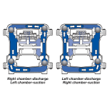
A lobe pump operates similarly to a gear pump, but with two lobes driven by external timing gears. Wolves don't make contact.
A progressive cavity pump consists of a metal rotor rotating inside an elastomer or rubber coated stator. As the rotor rotates, progressive chambers from the suction end to the discharge end are formed between the rotor and stator, moving the fluid.
Source: https://www.engineeringtoolbox.com/positive-displacement-pumps-d_414.html